What type of HF antenna do I need?
- Type of aircraft
- Location of antenna coupler
More or less, HF antenna configurations fall into four categories:
“V” and long wire configuration
The “V” and long wire antenna configuration is the optimal HF antenna configuration. It provides consistent performance and efficiency. This configuration should not be used on very high speed fixed wing aircraftand helicopters.
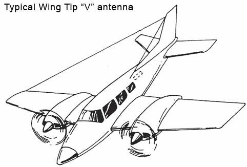
The wing “V” configuration is an effective HF antenna configuration for slow and moderate speed aircraft. This configuration provides an omnidirectional radiation
Pattern. It has has the disadvantages of high drag and on low wing aircraft is prone to being walked into.
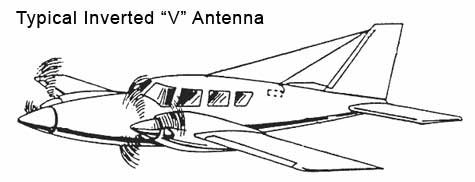
The inverted “V” antenna is recommended when a wing "V" is not practical and the antenna coupler is mounted in the back of the aircraft. The inverted “V” antenna will produce maximum signal
strength off the side of the aircraft and provide good efficiency at most frequencies. The inverted “V” produces a moderate amount of drag.
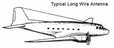
The long wire antenna is used when the HF coupler is located in the forward part of the aircraft. The long wire provides maximum signal radiation off the sides of
the aircraft and exhibit good efficiency even at the lower frequencies. Nulls in signal strength may be experienced off the nose and tail of the aircraft.
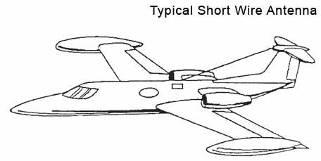
Short grounded wire configuration
Short grounded wire antennas are primarily used on higher speed and/or high altitude aircraft. The short wire antenna have minimum drag and do not develop as high of RF voltages as the longer wire antennas. However the efficiency of the short antenna will be lower, especially at the low frequencies.
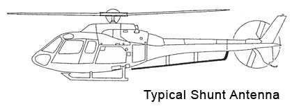
Shunt configuration
There a generally 2 types of shunt antennas. A towel bar style includes a rod or tube mounted on the airframe usually suited for helicopters.
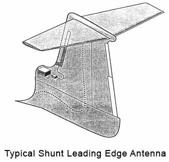
The other type of shunt antenna is designed by the aircraft manufacturer as a part of the airframe structure on the leading edge of the vertical stabilizer. Leading edge antennas are ideal for
Larger, high altitude jet aircraft.
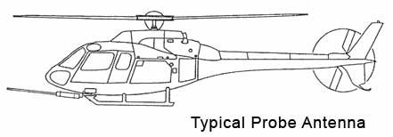
Probe configuration
Probe HF antennas are ideal on aircraft where a long antenna is not suitable. It should be noted that probe antennas provide poor efficiency at lower frequencies as is the case with most short style antennas.