

| Part #: | 064-1017-00 |
|---|---|
| Model: | KAC-952 |
| Desc: | HF Antenna Coupler |
| OEM: | BendixKing |
| NSN: | 5821-01-185-7531 |
|---|---|
| Sched-B: | 8543709610 |
| ECCN: | 7A994 |
| Cage Code: | 22373 |
| Price | Condition | Availability | Stock Info | |
|---|---|---|---|---|
| Price | Cond. | Avail. | Stock Info | |
| $3,950.00 | OH OUTRIGHT | IN WORK |
|
|
| $3,250.00 | OH EXCHANGE | IN WORK |
|
| Price | Condition | Availability | Stock Info | |
|---|---|---|---|---|
| Price | Cond. | Avail. | Stock Info | |
| $4,950.00 | OH OUTRIGHT | 2 IN STOCK |
Serial #: 13073 [Details]
Serial #: 15476 [Details]
|
|
| $2,950.00 | OH EXCHANGE | 2 IN STOCK |
Serial #: 13073 [Details]
Serial #: 15476 [Details]
|
| Price | Condition | Availability | Stock Info | |
|---|---|---|---|---|
| Price | Cond. | Avail. | Stock Info | |
| $5,650.00 | OH OUTRIGHT | REQUEST LEAD TIME |
|
|
| $3,250.00 | OH EXCHANGE | REQUEST LEAD TIME |
|
| Price | Condition | Availability | Stock Info | |
|---|---|---|---|---|
| Price | Cond. | Avail. | Stock Info | |
| REQUEST | OH OUTRIGHT | REQUEST LEAD TIME |
|

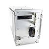
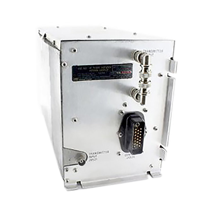
KAC-952
FEATURES
- Power Amplifier/Coupler unit for use with KHF-950 HF system
- Used in conjunction with KTR-953 receiver/exciter & either KCU-951 or KFS-594 controls
- Rugged aluminum diecast casing, modular contruction
- Models available with explosion proof casing design to meet TSO Explosion Proof requirement of DO-160 (see table below)
- Models available with external tuning capability through external capacitor connectors to support KA-161/162 adapters; shunt antenna configuration (see table below)
- Models produced that are only compatible with KCU-1051 Control with ALE (Automatic Link Establishment)
- May be mounted in unpressurized area to 55,000 feet
- 28V
- TSO'd
SPECIFICATIONS
| Size: | 5.75"W x 7.24"H x 14.25"L | Weight: | 12.5 lbs. |
| Antenna Coupler Characteristics: | Will match open wire antennas, 20 to 75 feet in length and grounded antennas, 10 to 25 feet in length throughout the frequency range. Grounded antennas are recommended for operation above 30,000 feet | Temperature Range: | -55C to +70C |
| TSO Compliance: | FAA TSO C-31c and C-32c | Altitude: | to 55,000 feet |
| Part Number: | Description: |
|---|---|
| 064-1017-00 | Basic model without external capacitor connector |
| 064-1017-01 | Without external capacitor connector, explosion proof |
| 064-1017-02 | With external capacitor connector, explosion proof |
| 064-1017-10 | Without external capacitor connector, compatible only with KCU-1051 control |
| 064-1017-11 | Without external capacitor connector, explosion proof, compatible only with KCU-1051 control |
| 064-1017-12 | With external capacitor connector, explosion proof, compatible only with KCU-1051 control |
| Price | Condition | Status |
|---|---|---|
| $4,950.00 | OH OUTRIGHT | 2 IN STOCK |
| $2,950.00 | OH EXCHANGE | 2 IN STOCK |
NSN: 5821-01-185-7531
| Price | Condition | Status |
|---|---|---|
| $3,950.00 | OH OUTRIGHT | IN WORK |
| $3,250.00 | OH EXCHANGE | IN WORK |
| Price | Condition | Status |
|---|---|---|
| REQUEST | OH OUTRIGHT | REQUEST LEAD TIME |
Click on a question below to see the answer. If you have a question about this model that is not answered below, please contact questions@seaerospace.com
Why do some parts indicate "REQUEST" or “RFQ” on the Southeast Aerospace website?
In relation to NE (New) parts, many OEMs change their prices and availability without any notice to dealers or the industry. Therefore, through the REQUEST or RFQ indication, we ask that customers contact us for the most accurate price and availability.
In relation to SV & OH parts, the used parts aftermarket in the aviation industry is not an infinite supply. It is a dynamic, constantly changing market that is significantly affected by and susceptible to highs and lows in supply and demand. Therefore, although we attempt to, at times, we are unable to predict the exact moment when an item may be available. Once again, through the REQUEST or RFQ indication on our website, we ask that customers contact us for the most current and accurate price and availability.
What is the difference between Honeywell (Bendix/King) part numbers with 9 digits vs. 12 digits?
Why are KHF-950 components with the letter P in the serial number undesirable?
Why are KHF-950 components below serial number 1500 undesirable?
Why did Bendix/King change their part numbers from a 9 digit to a 12 digit format?
Different software versions imply different operational features and/or interface capabilities and software modifications imply software repairs (bug fixes) to insure proper operation of these features and interfaces. Software version upgrades frequently require hardware modifications to the unit. Such hardware modifications accompanying software version upgrades do not necessarily change the hardware version of the unit.
Can the KHF-950 be installed into a helicopter?
A shorted tranline often referred to as "towel bar" antennas are best suited for helicopter applications. Towel bar antennas are attached parallel to the tailboom and fed in on the forward end (please see below example). Very specific instructions in relation to spacing, antenna construction, length, and mounting surface should be followed in order to minimize poor efficiencies at the low frequencies.
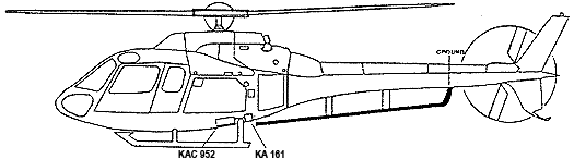
Since the towel bar style antenna is considered a short or shunt type HF antenna, the -02 version of the KAC-952 antenna coupler along with the KA-161 external capacitor must be utilized in this type of installation.
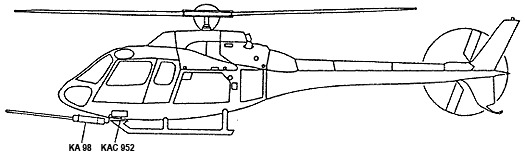
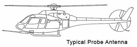
In certain installations, a towel bar style antenna may not be possible. Therefore, the KA-98 probe antenna may be used in the KHF-950 system. The same installation considerations (as mentioned above) would need to be observed since all short antennas provide poor efficiencies at low frequencies. A rod style antenna element is installed onto the front of the KA-98 (see picture below). It is important that the probe antenna be provided with a good RF ground. Therefore, the coax feedline from the KAC-952 coupler to the KA-98 cannot exceed 18 inches. In addition, the KA-98 can only be used with the -02 version of the KAC-952 and the KA-161 external capacitor to allow the antenna to tune more efficiently.
If this 18 inch requirement cannot be met, then the KHF-990 HF system should be considered since the amplifier is built in to the KAC-992 probe antenna coupler.
Can the KAC-992 probe antenna coupler be used with a KHF-950 system?
No. The following is a detailed explanation of some of the technical aspects within the KHF-950 and KHF-990 that prevent the KAC-992 from being used in the KHF-950 system.
The standard KHF-950 consists of the KCU-951 Control, KTR-953 Receiver Exciter, and KAC-952 Power Amplifier/Coupler.
In the transmit mode of operation, the KTR-953 provides a low power (milliwatts) signal (at the selected frequency) to the KAC-952. This excitation signal is amplified in the KAC-952 to provide the rated output power (watts). The power amplifier is contained in the KAC-952. The KAC-952 also tunes the antenna to the desired frequency by electronically varying the antenna’s length.
The standard KHF-990 system consists of a KFS-594 control, KTR-993 R/T, and KAC-992 probe antenna coupler.
The receiver/exciter and power amplifier is contained in the KTR-993. The output of the KTR-993 is the amplified RF signal at the rated power (watts). The KAC-992 is strictly an antenna tuner and provides no amplification. Also, the KTR-953 would not provide the commands required to initiate the tuning cycle.
If the KTR-953 was installed with a KAC-992, the output of the KTR-953 would not supply adequate power to drive the KAC-992. Even if it was able to tune, the output power would be millwatts (1/1000) instead of a hundred watts.
What HF antenna would be suitable for a Cessna Citation?
5ARM300-11C Tension Unit
14379 Anti-Precip Wire (30 feet)
16390 Feedthru Assembly
3280 Anchor Kit
Please search individual parts on SEA's website for pricing.
The KHF-950 I recently installed will not tune, what could be the problem?
- Poor connection on antenna feed thru.
- Long wire broken (a wire can crack and not be visible because of the thick insulation)
- For a short antenna run where the termination point is grounded, the ground may have become disconnected
- The wire from the KAC-952 coupler to the antenna should only be 6 inches ideally. A length of 18 inches is the absolute maximum. If the antenna feedline is longer than this, the efficiency of the KAC-952 will be greatly reduced possibly causing tuning failures at certain frequencies.
For the KHF-950 system, can the KTR-953 and KAC-952 be mounted in different locations in an aircraft?
- Display flashing intermittently when the user tries to tune the HF
- Audio distorted when transmitting on AM or SSB
- Output power low and varies when measured with wattmeter
- KTR-953 Service Bulletin 8 is effective for units S/N 29974 and below. This SB consists of removing several parts, install some wires, and mounting an feedback board into the unit
- KAC-952 Service Bulletin 9 is effective for units S/N 14332 and below or units with an older control board. This SB consists of make changes to the ALC circuit.
- KAC-952 Service Bulletin 10 is effective for units S/N 14884 and below or units with an older control board. This SB is a continuation of the modifications performed on KAC-952 SB 9 and consists of replacing several resistors and capacitors in the unit.
For more information on these modifications, please contact an SEA service representative today.
Are SEA's Exchange prices negotiable?
Negotiating the exchange price of a unit only limits the allowable repair cap for the core unit. Southeast Aerospace's exchange transactions are based on the return of economically repairable core unit. Once the core is received and evaluated, the core repair cost incurred by SEA cannot exceed 75% of the original exchange price. That is, it cannot cost SEA more than 75% of the original OH/SV exchange price collected from the customer. Therefore, when and if an SEA exchange price is discounted, there is a risk that additional charges may be assessed once the core is returned and evaluated.
What type of HF antenna do I need?
- Type of aircraft
- Location of antenna coupler
More or less, HF antenna configurations fall into four categories:
“V” and long wire configuration
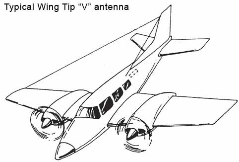
The “V” and long wire antenna configuration is the optimal HF antenna configuration. It provides consistent performance and efficiency. This configuration should not be used on very high speed fixed wing aircraftand helicopters.
The wing “V” configuration is an effective HF antenna configuration for slow and moderate speed aircraft. This configuration provides an omnidirectional radiation
Pattern. It has has the disadvantages of high drag and on low wing aircraft is prone to being walked into.
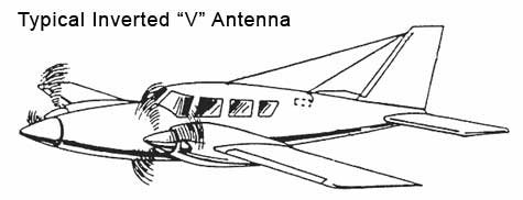
The inverted “V” antenna is recommended when a wing "V" is not practical and the antenna coupler is mounted in the back of the aircraft. The inverted “V” antenna will produce maximum signal
strength off the side of the aircraft and provide good efficiency at most frequencies. The inverted “V” produces a moderate amount of drag.
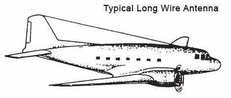
The long wire antenna is used when the HF coupler is located in the forward part of the aircraft. The long wire provides maximum signal radiation off the sides of
the aircraft and exhibit good efficiency even at the lower frequencies. Nulls in signal strength may be experienced off the nose and tail of the aircraft.
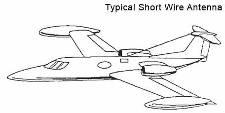
Short grounded wire configuration
Short grounded wire antennas are primarily used on higher speed and/or high altitude aircraft. The short wire antenna have minimum drag and do not develop as high of RF voltages as the longer wire antennas. However the efficiency of the short antenna will be lower, especially at the low frequencies.
Shunt configuration
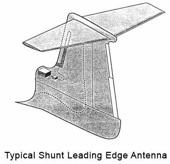
There a generally 2 types of shunt antennas. A towel bar style includes a rod or tube mounted on the airframe usually suited for helicopters.
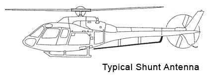
The other type of shunt antenna is designed by the aircraft manufacturer as a part of the airframe structure on the leading edge of the vertical stabilizer. Leading edge antennas are ideal for
Larger, high altitude jet aircraft.
Probe configuration
Probe HF antennas are ideal on aircraft where a long antenna is not suitable. It should be noted that probe antennas provide poor efficiency at lower frequencies as is the case with most short style antennas.
What rack do I use to mount the KAC-952 horizontally?
Is an STC required for an HF system installation?
HF installations in the USA are installed and approved in the method detailed above. STCs are not required for almost all HF installations since the change to the existing aircraft Type Certificate (TC) is not so intensive as to require one.
Why is the mod level important on the KTR-953 and KAC-952 HF components?
Previously, SEA answered the FAQ "...can the KTR-953 and KAC-952 be mounted in different locations in an aircraft". The answer to that question details the service bulletin (mod) levels that each unit must have incorporated for this installation scenario to be possible.
In addition to what these service bulletins offer in the way of installation flexibility, improper performance and actual unit failure can occur if the units are mismatched. KTR-953 units with SB 8 should only be paired with KAC-952 units with SB 9 & 10. KTR-953 without Mod 8 should only be paired with KAC-952 units without SB 9 & 10. Southeast Aerospace has actually seen units fail in the field when mismatched in this manner as well.
