
| Part #: | |
|---|---|
| Model: | GNS-530A |
| Desc: | GPS/Nav/Comm |
| OEM: | Garmin |
| NSN: | |
|---|---|
| Sched-B: | 8526910010 |
| ECCN: |
| Price | Condition | Availability | Stock Info | |
|---|---|---|---|---|
| Price | Cond. | Avail. | Stock Info | |
| REQUEST | SV EXCHANGE | REQUEST LEAD TIME |
|
| Price | Condition | Availability | Stock Info | |
|---|---|---|---|---|
| Price | Cond. | Avail. | Stock Info | |
| REQUEST | SV OUTRIGHT | REQUEST LEAD TIME |
|
|
| REQUEST | SV EXCHANGE | REQUEST LEAD TIME |
|
| Price | Condition | Availability | Stock Info | |
|---|---|---|---|---|
| Price | Cond. | Avail. | Stock Info | |
| REQUEST | SV EXCHANGE | REQUEST LEAD TIME |
|
| Price | Condition | Availability | Stock Info | |
|---|---|---|---|---|
| Price | Cond. | Avail. | Stock Info | |
| REQUEST | SV EXCHANGE | REQUEST LEAD TIME |
|

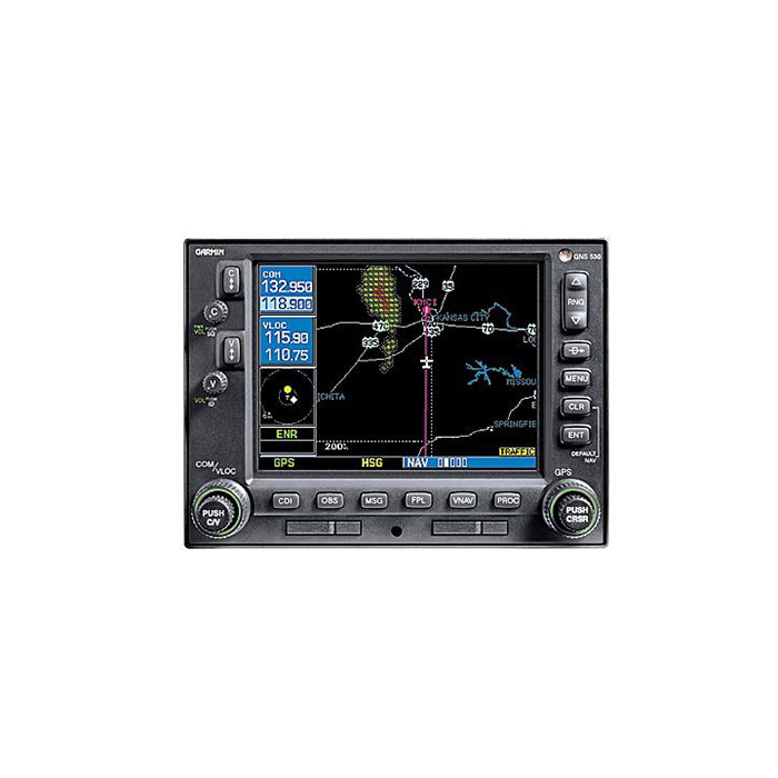
GNS 530A
FEATURES
- IFR GPS, 16 watt com, VOR, LOC and glideslope with color moving map in one unit
- TSO'd VHF Comm offers choice of 25 kHz or 8.33 kHz spacing
- Jeppesen database (front-loading data card) contains all airports, VORs, NDBs, intersections, FSS, Approach, SIDs/STARs, and SUA information
- 5" color display
- Offers enhanced situational awareness with relation to cities, highways, railroads, rivers, lakes and coastlines
- Use of color separates land data, terminal areas, route, and approach information for easy pilot scanning
- Able to interface with WX-500 stormscope for storm information
- Interfaces to Ryan 9900B / 9900BX TCAD and Goodrich Skywatch to display traffic information
- Scheduled to include Terrain Awareness information
- XM WX satellite weather service via GDL 69 available in 2005
- Non-TAWS terrain advisory feature available 2004/2005
- WAAS upgrade available via software/hardware upgrade 2004/2005
- Class B TAWS upgrade available- July 2004) - see Preliminary Drawing
Jeppesen Database
Coverage: Americas, International, or Worldwide
Airports: Identifier, city/state, country, facility name, lat/lon, elevation, fuel service, control, approach information
VORs: Identifier, city/state, country, facility name, lat/lon, frequency, co-located DME/TACAN, magnetic variation, weather broadcast indication
NDBs: Identifier, city/state, country, facility name, lat/lon, frequency, weather broadcast indication
Intersections: Identifier, country, lat/lon, nearest VOR
Frequencies: Approach, arrival, control area, departure, Class B, Class C, TMA, TRSA (with sector, altitude, and text usage), ASOS, ATIS, AWOS, center clearance delivery, tower, ground, unicom, pre-taxi, localizer, and ILS
Runways: Designation, length, width, surface, lighting, pilot-controlled lighting frequency
FSS: Identifier, reference VOR, frequency, usage
ARTCC: Identifier, frequency, usage
MSA: Minimum safe altitude along and in proximity to active flight plan
Approaches: Non-precision and precision approaches throughout the database coverage
SIDs/STARs: Contains all pilot/nav SIDs/STARs
Airspaces: Class B & C with sectors, International CTA & TMA with sectors, all SUAs, including MOAs, prohibited and restricted areas with controlling agency and airport
Safety Features
Emergency Search: 9 nearest airports, VORs, NDBs, intersections, or user waypoints; 2 nearest FSS and ARTCC frequencies
Alarms: Arrival and CDI, timers, SUAs less than 10 min, 2NM and inside SUA
User Customization
Waypoints: 1,000 User Defined
Flight Plans: 20 reversible routes of up to 31 waypoints each
Certification
GPS: TSO C129a, Class A1 (en route, terminal, and approach)
VOR: TSO C40c
LOC: TSO C36e
GS: TSO C34e
VHF COM: TSO C37d, Class 4 and 6 (transmit) and TSO C38d, Class C and E (receiver)
GPS Performance:
- Position: 15 meters (49 feet) RMS*, 1-5 meters with differential corrections
- Velocity: 0.1 knot RMS steady state
- Velocity: 999 knots
- Acceleration: 6g's
Receiver: twelve parallel channel receiver simultaneously tracks and uses up to 12 satellites
Acquisition Time: 12 seconds (warm), 45 seconds (cold)
Update Rate: Once per second, continuous
Accuracy:
Dynamics:
Nav Features: Pilot-defined Course Selection and Waypoint Hold, Closest Point of Approach, Departure and Arrival Frequencies, Approach Navigation using published approach procedures stored on NavData card, Terminal Navigation using SIDs/STARs from NavData card
Planning Features: True Airspeed, Density Altitude, Winds Aloft, RAIM Availability, Sunrise/Sunset Times, Trip and Fuel Planning, Vertical Navigation (VNAV)
Interfaces: ARINC 429, Aviation RS-232, CDI/HSI, RMI (digital: clock/data); Superflag Out, Altitude (serial: Icarus, Shadin-Rosetta, encoded Gillham/Greycode), Fuel Sensor, Fuel/Air Data
Map Datums: 124 and 1 user-defined
VOR Performance
Frequency Range: 108.00 MHz to 117.95 MHz
VOR/LOC Composite: 0.50Vrms/0.35Vrms
CDI Output: plus or minus 150mV Full Scale
Centering Accuracy: plus or minus 2.0 degrees
Flag Sensitivity: -103.5 dBm
DME Channeling: 2x5 available, Slip Code, BCD, King Serial
Audio Sensitivity -103.5 dBm for 6 dB S/N with 1 kHz 30% mod.
Audio Output: 100 mW (minimum) into 500 ohm load; External amplifier required
GS Performance
Frequency Range: 329.15 MHz to 335.00 MHz
CDI Output: plus or minus 150mV Full Scale
Centering Accuracy: 0 ddm plus or minus .0091 ddm
LOC Performance
Frequency Range: 108.10 MHz to 111.95 MHz
CDI Output: plus or minus 150mV Full Scale
Accuracy:
Flag Sensitivity: -103.5 dBm
Audio Sensitivity: -103.5 dBm for 6 dB S/N with 1 kHz 30% mod.
Audio Output: 100 mW (minimum) into 500 ohm load; External speaker amplifier required
VHF COM Performance
Frequency Display: Upper-left corner of active matrix LCD, 2-lines with active frequency above standby
Channels: 760 (25 kHz spacing); configuration for 3040 channels (8.33 kHz spacing) also provided
Frequency Range: 118.000 MHz to 136.975 MHz
Transmit Power: 10 watts (minimum)
Modulation: 70% (minimum)
Receive Sensitivity: 2.0 microvolts (hard) for 6 dB S/N with 1 kHz 30% mod.
Squelch Sensitivity: 2.0 microvolts (hard) typical
Audio Output: 100 mW (minimum) into a 500 ohm load; External speaker amplifier required
Certifications
GPS: TSO C129a A1
VOR: TSO C40c
LOC: TSO C36e
GS: TSO C34e
VHF COM: TSO C37d, Class 4 and 6 (transmit) and TSO C38d, Class C and E (receive)
Physical Specifications
Unit Size: Width = 6.25"; Height = 4.30"; Depth = 11.00" behind panel, with connectors
Unit Weight: 7.0 pounds installed
Display: Color LCD
Power: 14/28 VDC
Data Storage: Separate internal battery protects stored data for up to five years
Environmental
Temperature: -20°C to +55°C (operating range); -20°C to +70°C (short-term operation)
Humidity: 95% non-condensing
Altitude Range: -1,500 ft to 50,000 ft
| Part Number: | Description: |
|---|---|
| 010-00285-01 | GPS/Nav/Comm, black face |
| 010-00285-11 | GPS/Nav/Comm, gray face |
| Price | Condition | Status |
|---|---|---|
| REQUEST | SV EXCHANGE | REQUEST LEAD TIME |
| Price | Condition | Status |
|---|---|---|
| REQUEST | SV OUTRIGHT | REQUEST LEAD TIME |
| REQUEST | SV EXCHANGE | REQUEST LEAD TIME |
| Price | Condition | Status |
|---|---|---|
| REQUEST | SV EXCHANGE | REQUEST LEAD TIME |
| Price | Condition | Status |
|---|---|---|
| REQUEST | SV EXCHANGE | REQUEST LEAD TIME |
Click on a question below to see the answer. If you have a question about this model that is not answered below, please contact questions@seaerospace.com
Why do some parts indicate "REQUEST" or “RFQ” on the Southeast Aerospace website?
In relation to NE (New) parts, many OEMs change their prices and availability without any notice to dealers or the industry. Therefore, through the REQUEST or RFQ indication, we ask that customers contact us for the most accurate price and availability.
In relation to SV & OH parts, the used parts aftermarket in the aviation industry is not an infinite supply. It is a dynamic, constantly changing market that is significantly affected by and susceptible to highs and lows in supply and demand. Therefore, although we attempt to, at times, we are unable to predict the exact moment when an item may be available. Once again, through the REQUEST or RFQ indication on our website, we ask that customers contact us for the most current and accurate price and availability.
Does the Garmin GNS-530 contain interface capability for weather radar?
What indicators can be used with the Garmin GNS-430 and 530 Series Systems?
What software version is required for the processor of the Skywatch system to interface with the Garmin GNS-430/530?
Why aren't certain Garmin Avionics products available without installation?
What is required to upgrade the Garmin GNS-400/500 series GPS units to include WAAS?
There are several installation and certification issues including review of the STC approval from Garmin. This STC includes appendices detailing the approved equipment that can be interfaced to the WAAS capable units as well as approved installation diagrams for these interfaces.
The upgrade from Garmin includes the necessary updating of the unit, WAAS antenna, and new IFR-W Jeppesen database. The existing GPS antenna is replaced with the WAAS antenna. This WAAS antenna utilizes the same mounting holes however it should be noted that it is physically larger than the original GA-56 GPS antenna that was included with all GNS-400/500 series units. Also, in regards to the antenna installation, RG-142B or RG-400 coaxial cable must be used.
What is the difference between the classic Garmin GNS-400/500 GPS/Nav/Comms and the GNS-400W/500W units?
For a complete summary of the feature changes and enhancements, click Here.
What does the WAAS upgrade add to the classic GNS-400/500 series units?
Are there any additional benefits added to the GNS-400/500 series units during the WAAS upgrade?
If the terrain advisory feature is installed on the 400/500 series unit, then the terrain information will have a higher resolution.
When the GDL69 datalink is interfaced to the WAAS upgraded units, the weather will cover the entire USA instead of just 250 miles. METARS are included in the waypoint section making it easier to see weather information for a particular destination. Installations using the GDL69A with music will now be able to view the title and artist name on the GNS display.
Lastly, the WAAS upgrade provides the ability to fly curved flight paths with a roll steering autopilot for pilots who wish to utilize DME arcs or full approaches.
What are some of the other issues that need to be addressed when upgrading the GNS-400/500 series to include WAAS capability?
For aircraft with dual GNS-400/500 series units, both units must be upgraded for the crossfill function to operate. A WAAS upgraded 400/500 series unit will not crossfill to a non-WAAS 400/500 series unit.
One subject that many people upgrading to WAAS may overlook involves the GPS navigators distance from the pilot's primary field of view. The original GNS-400/500 series installation guidelines only provided general suggested guidelines for the distance of the unit from the pilot's primary view. Page 2- of the WAAS GNS-400/500 installation instructions is very specific in regards to the suggested guidelines for this distance. The left edge of the GNS unit should be no more than 11.8 inches from the centerline of the pilot's field of view. The 500 series units allow 12.1 inches. Vertically, the top of the GNS unit cannot be lower than the bottom edge of the primary flight instruments. If these measurements are exceeded then an additional annunciator may need to be installed near the pilot's primary field of view.
There are several wiring changes that need to be made to make the Bendix King KAP-140 / KFC-225 autopilots and original Sandel SN3308 EHSI completely compatible with the WAAS upgraded units. Certain features regarding proper navigation deviation will not function properly unless wiring changes are made in the aircraft. In addition, aircraft with more recent glass cockpit technology (e.g. EX5000 and G1000) have not been completely addressed for the WAAS upgrades.
In order to ensure that you receive the most accurate and realistic quotation for this WAAS upgrade, we strongly suggest that you contact our Installation Department for further assistance.
How do I update the database in my Garmin GPS?
For handheld GPS receivers, database updates can be ordered and downloaded directly through Garmin's Internet site.
For panel mount GPS receivers, all database cards and computer downloads (if applicable) must be ordered through Jeppesen. Contact Jeppesen at www.jeppesen.com for more information.
How do Garmin GNS-400/500 series part numbers change when upgraded to WAAS?
Do the Garmin GNS400/500 series navigators meet BRNAV requirements?
Does the GNS430/530 need to be configured before use?
What is the meaning of the N in some Garmin part numbers?
Can the standard GNS-430/530 and GNS-430W/530W units be upgraded to A versions?
