


| Part #: | 011-01065-40 |
|---|---|
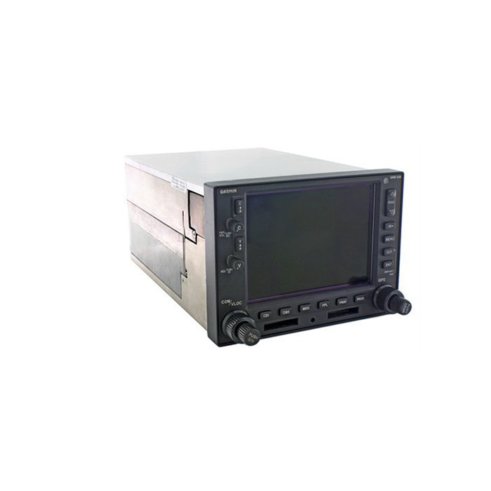
| Model: | GNS-530W |
| Desc: | WAAS GPS/Nav/Comm |
| OEM: | Garmin |
| NSN: | |
|---|---|
| Sched-B: | 8526910010 |
| ECCN: | 7A994 |
| Price | Condition | Availability | Stock Info | |
|---|---|---|---|---|
| Price | Cond. | Avail. | Stock Info | |
| $7,950.00 | SV OUTRIGHT | 1 IN STOCK |
Serial #: 23822798 [Details]
|
|
| $3,550.00 | SV EXCHANGE | 1 IN STOCK |
Serial #: 23822798 [Details]
|
| Price | Condition | Availability | Stock Info | |
|---|---|---|---|---|
| Price | Cond. | Avail. | Stock Info | |
| $7,950.00 | SV OUTRIGHT | 4 IN STOCK |
Serial #: 78407283 [Details]
Serial #: 78407856 [Details]
See More Stock
|
|
| $3,550.00 | SV EXCHANGE | 4 IN STOCK |
Serial #: 78407283 [Details]
Serial #: 78407856 [Details]
See More Stock
|
| Price | Condition | Availability | Stock Info | |
|---|---|---|---|---|
| Price | Cond. | Avail. | Stock Info | |
| $2,950.00 | SV EXCHANGE | 4 IN STOCK |
Serial #: 78404366 [Details]
Serial #: 78403311 [Details]
See More Stock
|
|
| $9,750.00 | SV OUTRIGHT | 4 IN STOCK |
Serial #: 78404366 [Details]
Serial #: 78403311 [Details]
See More Stock
|

GNS-530W
- Click Here to view a detailed comparison of the GNS-530W vs the GTN-750
- Announced as discontinued from the manufacturer as of October 31, 2011, expected to no longer be available by mid 2012
- Complies with WAAS TSO C146a
- Advisory Terrain Upgrade Available
- Terrain database for terrain awareness is standard
- WAAS GPS receiver allows for primary navigation and vertical guidance for LPV, L/VNAV, and LNAV+V approaches
- IFR GPS, com, VOR, LOC and glideslope with color moving map in one unit
- TSO'd VHF 10 watt Comm offers choice of 25 kHz or 8.33 kHz spacing
- Jeppesen database (front-loading data card) contains all airports, VORs, NDBs, intersections, FSS, Approach, SIDs/STARs, and SUA information
- 5" color display
- Offers enhanced situational awareness with relation to cities, highways, railroads, rivers, lakes and coastlines
- Use of color separates land data, terminal areas, route, and approach information for easy pilot scanning
- Able to interface with WX-500 stormscope for storm information
- Interfaces to Ryan 9900B / 9900BX TCAD and Goodrich Skywatch to display traffic information
- Class B TAWS version and upgrade available
**Click Here to download the GNS-530 Quick Reference Guide **Click Here to download the GNS-530 Pilots Guide
Jeppesen Database
Coverage: Americas, International, or Worldwide
Airports: Identifier, city/state, country, facility name, lat/lon, elevation, fuel service, control, approach information
VORs: Identifier, city/state, country, facility name, lat/lon, frequency, co-located DME/TACAN, magnetic variation, weather broadcast indication
NDBs: Identifier, city/state, country, facility name, lat/lon, frequency, weather broadcast indication
Intersections: Identifier, country, lat/lon, nearest VOR
Frequencies: Approach, arrival, control area, departure, Class B, Class C, TMA, TRSA (with sector, altitude, and text usage), ASOS, ATIS, AWOS, center clearance delivery, tower, ground, unicom, pre-taxi, localizer, and ILS
Runways: Designation, length, width, surface, lighting, pilot-controlled lighting frequency
FSS: Identifier, reference VOR, frequency, usage
ARTCC: Identifier, frequency, usage
MSA: Minimum safe altitude along and in proximity to active flight plan
Approaches: Non-precision and precision approaches throughout the database coverage
SIDs/STARs: Contains all pilot/nav SIDs/STARs
Airspaces: Class B & C with sectors, International CTA & TMA with sectors, all SUAs, including MOAs, prohibited and restricted areas with controlling agency and airport
Safety Features
Emergency Search: 9 nearest airports, VORs, NDBs, intersections, or user waypoints; 2 nearest FSS and ARTCC frequencies
Alarms: Arrival and CDI, timers, SUAs less than 10 min, 2NM and inside SUA
User Customization
Waypoints: 1,000 User Defined
Flight Plans: 20 reversible routes of up to 31 waypoints each
Certification
GPS: TSO C129a, Class A1 (en route, terminal, and approach)
VOR: TSO C40c
LOC: TSO C36e
GS: TSO C34e
VHF COM: TSO C37d, Class 4 and 6 (transmit) and TSO C38d, Class C and E (receiver)
GPS Performance:
- Position: 15 meters (49 feet) RMS*, 1-5 meters with differential corrections
- Velocity: 0.1 knot RMS steady state
- Velocity: 999 knots
- Acceleration: 6g's
Receiver: twelve parallel channel receiver simultaneously tracks and uses up to 12 satellites
Acquisition Time: 12 seconds (warm), 45 seconds (cold)
Update Rate: Once per second, continuous
Accuracy:
Dynamics:
Nav Features: Pilot-defined Course Selection and Waypoint Hold, Closest Point of Approach, Departure and Arrival Frequencies, Approach Navigation using published approach procedures stored on NavData card, Terminal Navigation using SIDs/STARs from NavData card
Planning Features: True Airspeed, Density Altitude, Winds Aloft, RAIM Availability, Sunrise/Sunset Times, Trip and Fuel Planning, Vertical Navigation (VNAV)
Interfaces: ARINC 429, Aviation RS-232, CDI/HSI, RMI (digital: clock/data); Superflag Out, Altitude (serial: Icarus, Shadin-Rosetta, encoded Gillham/Greycode), Fuel Sensor, Fuel/Air Data
Map Datums: 124 and 1 user-defined
VOR Performance
Frequency Range: 108.00 MHz to 117.95 MHz
VOR/LOC Composite: 0.50Vrms/0.35Vrms
CDI Output: plus or minus 150mV Full Scale
Centering Accuracy: plus or minus 2.0 degrees
Flag Sensitivity: -103.5 dBm
DME Channeling: 2x5 available, Slip Code, BCD, King Serial
Audio Sensitivity -103.5 dBm for 6 dB S/N with 1 kHz 30% mod.
Audio Output: 100 mW (minimum) into 500 ohm load; External amplifier required
GS Performance
Frequency Range: 329.15 MHz to 335.00 MHz
CDI Output: plus or minus 150mV Full Scale
Centering Accuracy: 0 ddm plus or minus .0091 ddm
LOC Performance
Frequency Range: 108.10 MHz to 111.95 MHz
CDI Output: plus or minus 150mV Full Scale
Accuracy:
Flag Sensitivity: -103.5 dBm
Audio Sensitivity: -103.5 dBm for 6 dB S/N with 1 kHz 30% mod.
Audio Output: 100 mW (minimum) into 500 ohm load; External speaker amplifier required
VHF COM Performance
Frequency Display: Upper-left corner of active matrix LCD, 2-lines with active frequency above standby
Channels: 760 (25 kHz spacing); configuration for 3040 channels (8.33 kHz spacing) also provided
Frequency Range: 118.000 MHz to 136.975 MHz
Transmit Power: 10 watts (minimum)
Modulation: 70% (minimum)
Receive Sensitivity: 2.0 microvolts (hard) for 6 dB S/N with 1 kHz 30% mod.
Squelch Sensitivity: 2.0 microvolts (hard) typical
Audio Output: 100 mW (minimum) into a 500 ohm load; External speaker amplifier required
Certifications
GPS: TSO C129a A1
VOR: TSO C40c
LOC: TSO C36e
GS: TSO C34e
VHF COM: TSO C37d, Class 4 and 6 (transmit) and TSO C38d, Class C and E (receive)
Physical Specifications
Unit Size: Width = 6.25"; Height = 4.30"; Depth = 11.00" behind panel, with connectors
Unit Weight: 7.0 pounds installed
Display: Color LCD
Power: 14/28 VDC
Data Storage: Separate internal battery protects stored data for up to five years
Environmental
Temperature: -20°C to +55°C (operating range); -20°C to +70°C (short-term operation)
Humidity: 95% non-condensing
Altitude Range: -1,500 ft to 50,000 ft
| Part Number: | Description: |
|---|---|
| 011-01064-00 | WAAS GPS/Nav/Comm, Black, 14/28V |
| 011-01064-10 | WAAS GPS/Nav/Comm, Gray, 14/28V |
| 011-01064-40 | Black, 14/28V, Upgrade from non-WAAS unit |
| 011-01064-45 | Black, 28V, Upgrade from non-WAAS unit |
| 011-01064-50 | Gray, 14/28V, Upgrade from non-WAAS unit |
| 011-01065-00 | WAAS GPS/Nav/Comm, Black, 14/28V w/ TAWS |
| 011-01065-10 | WAAS GPS/Nav/Comm, Gray, 14/28V w/ TAWS |
| 011-01065-40 | Black, 14/28V w/ TAWS, Upgrade from non-WAAS unit |
| 011-01065-45 | Black, 28V only, w/ TAWS, Upgrade from non-WAAS unit |
| 011-01065-50 | Gray, 14/28V w/ TAWS, Upgrade from non-WAAS unit |
| Serial # | 78404366 |
|---|---|
| Condition | SV |
| Mods | 1-6 |
| Tag Date | 06/04/26 |
| Shop | Southeast Aerospace Inc. |
| Warranty | 6 Months |
| Serial # | 78403311 |
|---|---|
| Condition | SV |
| Mods | 1-4 |
| Tag Date | 08/01/25 |
| Shop | Southeast Aerospace Inc. |
| Warranty | 6 Months |
| Serial # | 85200444 |
|---|---|
| Condition | SV |
| Mods | 1-6 |
| Tag Date | 08/01/25 |
| Shop | Southeast Aerospace Inc. |
| Warranty | 6 Months |
| Serial # | 78404350 |
|---|---|
| Condition | SV |
| Mods | 1-6 |
| Tag Date | 07/17/25 |
| Shop | Southeast Aerospace Inc. |
| Warranty | 6 Months |
| Price | Condition | Status |
|---|---|---|
| $7,950.00 | SV OUTRIGHT | 4 IN STOCK |
| $3,550.00 | SV EXCHANGE | 4 IN STOCK |
| Price | Condition | Status |
|---|---|---|
| $2,950.00 | SV EXCHANGE | 4 IN STOCK |
| $9,750.00 | SV OUTRIGHT | 4 IN STOCK |
| Price | Condition | Status |
|---|---|---|
| $7,950.00 | SV OUTRIGHT | 1 IN STOCK |
| $3,550.00 | SV EXCHANGE | 1 IN STOCK |
Click on a question below to see the answer. If you have a question about this model that is not answered below, please contact questions@seaerospace.com
Can you please explain in detail the difference between Garmin part numbers that begin with 010 versus Garmin part numbers that begin with 011?
Southeast Aerospace has created a document that explains in detail the difference between the 010 vs. 011 part numbers.
Please see link: SEA-Garmin-010-and-011-FAQ.pdf
When did Garmin stop supporting the 28 Volt versions of the GNS-430/530 series units?
According to Garmin Support Memo dated July 21, 2010, effective September 30, 2010, the 28 Volt only versions of the GNS-430/530 series units will no longer be repaired due to parts availability issues.
The 28 Volt only versions of the GNS series units are the very first original productions units from the late 1990s.
Why do some parts indicate "REQUEST" or “RFQ” on the Southeast Aerospace website?
In relation to NE (New) parts, many OEMs change their prices and availability without any notice to dealers or the industry. Therefore, through the REQUEST or RFQ indication, we ask that customers contact us for the most accurate price and availability.
In relation to SV & OH parts, the used parts aftermarket in the aviation industry is not an infinite supply. It is a dynamic, constantly changing market that is significantly affected by and susceptible to highs and lows in supply and demand. Therefore, although we attempt to, at times, we are unable to predict the exact moment when an item may be available. Once again, through the REQUEST or RFQ indication on our website, we ask that customers contact us for the most current and accurate price and availability.
How can I safely clean and disinfect my Garmin avionics?
Garmin has provided Service Advisory 2051 for general recommendations, materials, and supplies to clean and disinfect Garmin products. Otherwise, not following the recommendations could void the warranty.
- Cleaners containing ammonia will harm the anti-reflective coating on many Garmin aviation display lenses.
- Disinfectant with a solution of 70% isopropyl alcohol that does not contain ammonia is preferred. Solutions of up to 91% isopropyl alcohol are also acceptable.
- Clean the display lens using a clean lint-free cloth and a cleaner that is specified as safe for anti-reflective coatings.
- For other exposed surfaces such as knobs, buttons, and bezels, a damp cloth with soap and water is acceptable.
- Bleach-based cleaners, ammonia-based cleaners, or other harsh chemicals on any surface are not recommended.
- Remove all soap/soap residue to prevent buttons and knobs from gumming up or becoming slippery.
- Many aviation products are not rated as waterproof. Spraying or wetting the units to the extent where moisture could go beyond the exterior surfaces could damage the unit.
I want to upgrade my PA24-260 Piper Comanche nav/com to a GNS-530W as well as making it ADS-B in/out compliant. What transponder and other components are required?
First, we would recommend contacting a local Garmin dealer to discuss the following:
- Upgrading your existing nav/com to a used GNS-530W or the newer GTN-750.
- If you already have a Garmin transponder (i.e. GTX-330), then you should simply get the ES upgrade, interface to GNS-530W or GTN-750, along with a few other minor installation considerations, and get the shop to do the appropriate paperwork based on Garmin's AML STC.
- If you do not have the GTX-330, then you should just consider pursuing one of the GDL systems from Garmin. Most likely the GDL88 which will give you In/Out capability. Same interface and installation considerations as above apply. Please note ADS-B In is not required for the mandate.
Why does the traffic thumbnail for my 400 or 500 series aviation device say "See Map"?
Traffic can be displayed in two different map views on the 400 and 500 series aviation devices. The thumbnail view is always in a track-up reference while the map view can be in either a track-up or north-up reference. To see traffic simultaneously on the map and on the thumbnail, the orientation of the map must be set to track-up. Otherwise, traffic will only be shown on the map and the thumbnail will say "See Map".
What is the difference between the legacy 400/500 series units and the WAAS 400w/500w series units?
The WAAS systems have the same capabilities as the 400/500 systems plus a few more. With the WAAS signal being acquired, the GPS can give vertical guidance to a runway similar to an ILS glide slope indication. The WAAS units have added display capability when connected to our GDL-69/A XM Satellite weather/radio receiver. They also have additional ARINC 424 leg types to guide a compatible autopilot through procedure turns and published holds.
Why is the altitude on my GNS-530W different than the altitude on my altimeter?
An altimeter does not measure altitude on the Garmin GPS device. The altimeter in the aircraft measures air pressure. The altimeter is calibrated to display a certain change in altitude based on a change in air pressure. For every inch of mercury pressure change, the altimeter displays a change of approx. 1000 ft. of altitude. The GPS does not use air pressure to determine altitude and is not subject to the pressure errors in determining altitude. Therefore, the GPS derived altitude is almost always more accurate than an altimeter. Since everyone uses a pressure-based system to determine altitude, it is integral to utilize a pressure sensitive altimeter to ensure required vertical separation.
What is the difference between Terrain Advisory and TAWS?
Can the standard GNS-430/530 and GNS-430W/530W units be upgraded to A versions?
Does the GTN 750 replace the discontinued GNS-530W? What is the difference between the two?
The GTN 750 is a replacement for the GNS-530W. You can compare the two units here
What is the meaning of the N in some Garmin part numbers?
I need an affordable IFR GPS system, which one should I purchase?
See this PDF document for a detailed listing of currently available IFR GPS systems and a brief comparison.
Why aren't certain Garmin Avionics products available without installation?
What type of traffic systems will interface with and display on the Garmin GNS430/530 series systems?
What items are needed to install the GNS-430/430W/530/530W systems into my aircraft?
- GPS antenna (usually included when system is purchased)
- External CDI* for VOR/ILS navigation and glideslope information; required for IFR certification as well
- Nav antenna* for VHF Nav functions
- COMM antenna* for COMM functions
As with all avionics installations, other general materials are required for installation but not supplied with the standard system. These materials could include but are not limited to wire, mounting screws, circuit breakers, tie wraps, ring terminals, coaxial cable, hand crimping tools, and crimp positioner/insertion/extraction tools.
Does the GNS430/530 need to be configured before use?
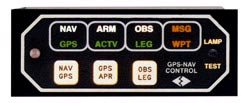
What is the function and reason for annunciators required in an IFR GPS installation?
TERM - light that will signal pilot when operating within 30 miles of departure or arrival airport (i.e. Terminal area)
APR - light that signals pilot when the GPS is engaged in Approach mode
MSG - light that signals pilot that the GPS has generated a Message alert that should be viewed on the GPS
WPT - light that signals pilot that the GPS has generated a Waypoint alert that should be viewed on the GPS
INTG - light that will signal pilot when the GPS receiver detects a position error or is unable to calculate the Integrity of the position
Some annunciator units and annunciator control units or ACUs have a variety a these switches and annunciators depending on the GPS system to be interfaced with or the aircraft installation. However, there are certain annunciations such as MSG and WPT that are standard for all annunciators required.
Do the Garmin GNS400/500 series navigators meet BRNAV requirements?
What is the main difference between the versions of Mid-Continent MD41 annunciators available?
The ACU units can be complete with control and relay built into one assembly or they can be separated depending on the part number. Some GPS systems and CDIs include internal relays. Therefore, only a control with switch is required. In this case, you would only purchase the Control Head. Some installations use different custom sizes and styles of annunciator switches. Therefore, in this case, only a remote relay is purchased without a control assembly.
 |
 |
 |
In addition to variations in switches, relays, and sizes, ACUs are engineered to be compatible with specific GPS systems by different manufacturers. Variations in power input and bezel orientation are available as well.
How do Garmin GNS-400/500 series part numbers change when upgraded to WAAS?
How do I update the database in my Garmin GPS?
For handheld GPS receivers, database updates can be ordered and downloaded directly through Garmin's Internet site.
For panel mount GPS receivers, all database cards and computer downloads (if applicable) must be ordered through Jeppesen. Contact Jeppesen at www.jeppesen.com for more information.
Will the new Garmin 400W/500W series WAAS units work with my EFIS?
Honeywell EFIS 40/50 with the SG 465 symbol generator with the following limitation: No vertical guidance is provided for GPS approaches.
Sandel SN3308 with the following limitation: GPS lateral and vertical guidance is provided using the analog interface.
Sandel SN3500 with the following limitation: Vertical guidance is provided for GPS approaches.
This is specified in the latest Garmin 400W series installation manual P/N 190-00356-02 Rev. C, dated April 2007.
What are the issues for interfacing the WX-500 Stormscope with Garmin WAAS GPS receivers?
Where can WAAS approach-capable GPS navigators be operated?
What is the difference between the classic Garmin GNS-400/500 GPS/Nav/Comms and the GNS-400W/500W units?
For a complete summary of the feature changes and enhancements, click Here.
