

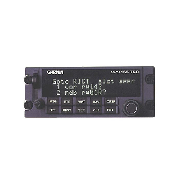
GPS 165
- DZUS mounted
- IFR Certified for en route and approach
- Jeppesen database includes airports, VOR's, NDB's, intersections, Comm frequencies, runways, FSS, MSA, SUA, approaches, and SIDs/Stars
- Three line vacuum-florescent dot matrix display
- 1000 user defined waypoints
- 20 reversible routes of up to 31 waypoints each
- Stoarge for 40 character comments on up to 250 waypoints
- 9 user checklists of up to 30 items each
- 9 schedules user messages
SPECIFICATIONS
| Emergency Search: | 9 nearest airports, VOR's, NDB's, intersections, or user waypoints; also displays nearest to current position and 2 nearest FSS and freq. | Alarms: | Arrival, Proximity, Timers, SUA's less than 10 min, 2NM and inside SUA |
| Receiver: | MultiTrac8; Tracks and uses up to 8 satellites to compute amd update position | Acquisition Time: | 3 minutes |
| Update Rate: | 1/second, continuous | Accuracy: | 15 meters |
| Interfaces: | Aviation (RS-232, RS-422, ARINC 429 (GAMA),plotting (NMEA 0183 v2.0), CDI/HIS; RMI digital: clock, data); Superflag output; Altitude (serial: Icarus, Shadin-Rosettea; encoded Gillham/Greycode) | Map Datums: | 124 predefined, 1 user defined |
| Size: | 5.75 x 2.25 x 5.65 inches | Weight: | 2.14 pounds |
| Certification: | TSO C129 Class A1 (enroute, terminal and approach) | Display: | High intensity, 600 foot Lambert, dot matrix fluorescent |
| Power Backup: | Built-in battery automatically powers unit in case of electric power failure | Navigation Features: | Search and rescue operation (ladder search), course selection capability via mechanicaland EFIS, HSI, Closest point of appraoch, approach navigation using published approach procedures stored on data crda, terminal naviagtion using SID/STAR from data card |
| Planning Features: | True airspeed, density altitude, winds aloft, RAIM availability, Sunrise/Sunset calculations, and trip, fuel and VNAV planning | Dynamics: | Velocity: 999 knots Acceleration: 3G |
| Part Number: | Description: |
|---|---|
| 010-00075-00 | DZUS Mount IFR GPS Receiver, Black |
| 010-00075-01 | DZUS Mount IFR GPS Receiver, Gray |
Click on a question below to see the answer. If you have a question about this model that is not answered below, please contact questions@seaerospace.com
Why do some parts indicate "REQUEST" or “RFQ” on the Southeast Aerospace website?
In relation to NE (New) parts, many OEMs change their prices and availability without any notice to dealers or the industry. Therefore, through the REQUEST or RFQ indication, we ask that customers contact us for the most accurate price and availability.
In relation to SV & OH parts, the used parts aftermarket in the aviation industry is not an infinite supply. It is a dynamic, constantly changing market that is significantly affected by and susceptible to highs and lows in supply and demand. Therefore, although we attempt to, at times, we are unable to predict the exact moment when an item may be available. Once again, through the REQUEST or RFQ indication on our website, we ask that customers contact us for the most current and accurate price and availability.
Why is the altitude on GPS-165 different than the altitude on my altimeter?
An altimeter does not measure altitude on the Garmin GPS device. The altimeter in the aircraft measures air pressure. The altimeter is calibrated to display a certain change in altitude based on a change in air pressure. For every inch of mercury pressure change, the altimeter displays a change of approx. 1000 ft. of altitude. The GPS does not use air pressure to determine altitude and is not subject to the pressure errors in determining altitude. Therefore, the GPS derived altitude is almost always more accurate than an altimeter. Since everyone uses a pressure-based system to determine altitude, it is integral to utilize a pressure sensitive altimeter to ensure required vertical separation.
How do I update the database in my Garmin GPS?
For handheld GPS receivers, database updates can be ordered and downloaded directly through Garmin's Internet site.
For panel mount GPS receivers, all database cards and computer downloads (if applicable) must be ordered through Jeppesen. Contact Jeppesen at www.jeppesen.com for more information.
What factors could be causing a newly installed or replacement avionics unit to not be working properly?
Autopilot
EFIS
GPS
EGPWS
EHSI
RADAR
TAWS
TCAS
In addition, most newer technology or solid state systems require configuration via computer interface of some type. A qualified avionics technician should always refer to the appropriate manufacturer's installation manual for complete information and instructions.
What is the main difference between the versions of Mid-Continent MD41 annunciators available?
The ACU units can be complete with control and relay built into one assembly or they can be separated depending on the part number. Some GPS systems and CDIs include internal relays. Therefore, only a control with switch is required. In this case, you would only purchase the Control Head. Some installations use different custom sizes and styles of annunciator switches. Therefore, in this case, only a remote relay is purchased without a control assembly.
 |
 |
 |
In addition to variations in switches, relays, and sizes, ACUs are engineered to be compatible with specific GPS systems by different manufacturers. Variations in power input and bezel orientation are available as well.
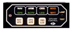
What is the function and reason for annunciators required in an IFR GPS installation?
TERM - light that will signal pilot when operating within 30 miles of departure or arrival airport (i.e. Terminal area)
APR - light that signals pilot when the GPS is engaged in Approach mode
MSG - light that signals pilot that the GPS has generated a Message alert that should be viewed on the GPS
WPT - light that signals pilot that the GPS has generated a Waypoint alert that should be viewed on the GPS
INTG - light that will signal pilot when the GPS receiver detects a position error or is unable to calculate the Integrity of the position
Some annunciator units and annunciator control units or ACUs have a variety a these switches and annunciators depending on the GPS system to be interfaced with or the aircraft installation. However, there are certain annunciations such as MSG and WPT that are standard for all annunciators required.
Are SEA's Exchange prices negotiable?
Negotiating the exchange price of a unit only limits the allowable repair cap for the core unit. Southeast Aerospace's exchange transactions are based on the return of economically repairable core unit. Once the core is received and evaluated, the core repair cost incurred by SEA cannot exceed 75% of the original exchange price. That is, it cannot cost SEA more than 75% of the original OH/SV exchange price collected from the customer. Therefore, when and if an SEA exchange price is discounted, there is a risk that additional charges may be assessed once the core is returned and evaluated.
I need an affordable IFR GPS system, which one should I purchase?
See this PDF document for a detailed listing of currently available IFR GPS systems and a brief comparison.
What is the meaning of the N in some Garmin part numbers?
