On September 13, 2019, Extant Aerospace reached an agreement to acquire the Stormscope product line of lightning detection systems from L3Harris. All manufacturing and support will now be handled by Extant Aerospace in Melbourne, Florida.
| Part #: | |
|---|---|
| Model: | WX-500 |
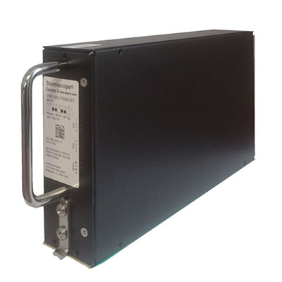
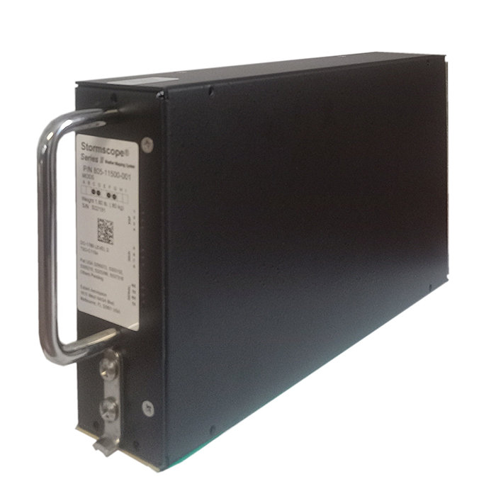
| Desc: | Stormscope Processor |
| OEM: | Extant Aerospace |
| NSN: | |
|---|---|
| Sched-B: | 8526100010 |
| ECCN: | |
| Cage Code: | 25583 |
Part Number :
| Price | Condition | Availability | Stock Info | |
|---|---|---|---|---|
| Price | Cond. | Avail. | Stock Info | |
| REQUEST | NEW OUTRIGHT | REQUEST LEAD TIME |
|
* Price & Availability valid as of 08/01/26 19:01:19 EDT *
| Price | Condition | Availability | Stock Info | |
|---|---|---|---|---|
| Price | Cond. | Avail. | Stock Info | |
| REQUEST | NEW OUTRIGHT | REQUEST LEAD TIME |
|
* Price & Availability valid as of 08/01/26 19:01:19 EDT *

FEATURES
- Plots lightning as it happens, before the onset of precipitation
- Displays lightning in 25, 50, 100 and 200 nmi ranges
- Pilot selectable Cell and Strike modes
- 360-degree view or 120-degree forward looking
- Updates lightning information every second
- Strike Rate indicator details building or dissipating storms
- Integrates with SkyWatch Collision Avoidance Systems
- Weight (Processor): 2.5 lbs. (1.13 kg)
| Part Number: | Description: |
|---|---|
| 805-11500-001 | Stormscope Processor |
805-11500-001
- Stormscope Processor
NSN: 5999-01-533-8554
| Price | Condition | Status |
|---|---|---|
| REQUEST | NEW OUTRIGHT | REQUEST LEAD TIME |
830-11500-001
- Stormscope System (w/ 6 ft cable)
| Price | Condition | Status |
|---|---|---|
| REQUEST | NEW OUTRIGHT | REQUEST LEAD TIME |
Click on a question below to see the answer. If you have a question about this model that is not answered below, please contact questions@seaerospace.com
Why do some parts indicate "REQUEST" or “RFQ” on the Southeast Aerospace website?
In relation to NE (New) parts, many OEMs change their prices and availability without any notice to dealers or the industry. Therefore, through the REQUEST or RFQ indication, we ask that customers contact us for the most accurate price and availability.
In relation to SV & OH parts, the used parts aftermarket in the aviation industry is not an infinite supply. It is a dynamic, constantly changing market that is significantly affected by and susceptible to highs and lows in supply and demand. Therefore, although we attempt to, at times, we are unable to predict the exact moment when an item may be available. Once again, through the REQUEST or RFQ indication on our website, we ask that customers contact us for the most current and accurate price and availability.
What are the installation considerations for Stormscope antenna installation?
Because Stormscope weather mapping systems detect electrical discharge activity, antenna placement relative to other active electrical components is critical. The antenna must be placed at a location that is free from excessive electrical interference. The ideal location varies for aircraft to aircraft. To ensure an interference-free antenna location, every aircraft must be skinmapped prior to installation of the Stormscope antenna. The skinmap must be done with the engines and all electrical systems operating. The Stormscope requirement for an antenna ground plane and a noise free environment complicates installation in aircraft with wood, fabric, or composite construction. Each aircraft needs to be analyzed individually for best antenna location. Avoid mounting the antenna near active electrical components whenever possible. General clearance guidelines are: - Strobe lamps and power supplies 5 ft. (1.5 meters) - Pitch trim servos and amplifiers 3 ft. (1 meter) - Fluorescent lamps and ballasts 5 ft. (1.5 meters) - Heater ignitors 5 ft (1.5 meters) - Air conditioner and heater blowers - DME/Transponder/TCAS antennas 4 ft. minimum (1.2 meters) - Inflight telephone antennas 4 ft (1.2 meters) - VHF comm antennas 1 ft. (.3 meters) - ADF antennas 1 ft. (.3 meters) - Any current carrying cable 2 ft. (0.6 meters) Stormscope sensors are adversely affected by the build up of static charges. Do not mount the antenna near any composite materials (e.g. plastic covers, radomes, fiberglass housings, windows, etc.) as these devices can build up static charges. Avoid mounting the antenna in the ground return current path between the battery and alternator, and the battery and blower motors of other heavy current carrying equipment. Aircraft skin currents may cause antenna interference.
What are the issues for interfacing the WX-500 Stormscope with Garmin WAAS GPS receivers?
Under certain conditions, the Garmin 400W/500W series units will not provide serial heading information to the L3 WX-500 Stormscope. Even if the WX-500 unit is wired for synchro heading, there may be issues with the WX-500, GDL-69 datalink, and crossfill between two Garmin units. Also, some issues have been encountered with the COM flip/flop key not switching between the active and standby frequencies. As of 8/20/07, Garmin plans to resolve these issue with the next software release. The software upgrade should be able to be completed at your local Garmin authorized facility.
What other equipment is required to properly install the WX-500 stormscope?
The WX-SM Skinmapper and WX-PA Portable Analyzer are required to properly install the WX-500.
The WX-SM Skinmapper is required to verify the ideal location for the WX-500 antenna. The antenna must be installed in a location on the aircraft that is free from electrical interference. The ideal location varies on each aircraft. The skinmapping must be performed with all engines and electrical systems operating.
The WX-PA Portable Analyzer is required to test the system after installation. The WX-PA analyzes the accuracy of strike and heading information for the stormscope system.
Is there a Flight Manual Supplement available for the WX-500?
No, the flight manual supplement from the manufacturer of the display being used to display the Stormscope information is used instead.
Click on a headline below to see more:
2019-09-13 Extant Aerospace Acquires Stormscope Product Line from L3Harris
